onshape sheet metal bending The Sheet metal table and flat view is where you can edit an existing sheet . $795.00
0 · sheet metal onshape
1 · sheet metal edges onshape
2 · onshape sheet metal pattern
3 · onshape sheet metal models
4 · onshape sheet metal depth
5 · onshape bend sheet metal
6 · onshape bend calculator
7 · onshape bend angle
Get the best deals for Vintage Metal Tackle Box. at eBay.com. We have a great online selection at the lowest prices with Fast & Free shipping on many items!
Sheet metal bend: Desktop. The bend feature folds sheet metal along a reference and is useful when traditional methods may be time consuming to add. For instance, creating .In this Tech Tip, we will explore the various bend calculation options available for .
By moving joints up and down in the Sheet Metal Table, you can capture your bend .Bend - Bend a sheet metal model along a reference line, with additional bend .The Sheet metal table and flat view is where you can edit an existing sheet .
I have a sheet metal part, and would like to add a bend somewhere in the middle of .In this Tech Tip, we will explore the various bend calculation options available for sheet metal, namely K Factor, bend allowance, and bend deduction, and guide you on when to use each.By moving joints up and down in the Sheet Metal Table, you can capture your bend order right inside the Onshape Document. No need for separate .
Bend - Bend a sheet metal model along a reference line, with additional bend control options. Make joint - Convert the intersection of two walls into a joint feature, either a bend (walls joined by cylindrical geometry) or a rip .Use sheet metal bend parameters like K-factor, bend allowances, and bend deductions, to ensure accurate flat pattern generation for your sheet metal designs. It's crucial for product manufacturability, ensuring precise dimensions . When it comes to Sheet Metal design in Onshape, mastering bend calculations is a key skill that can significantly impact the accuracy and manufacturability of your designs.
Is there a way to add a relief cut to sheet metal parts for where holes are located near a bend to prevent them from distorting during the bending process? Another application for this is to add a relief on a bend to allow the .

sheet metal onshape
Welcome to the Onshape forum! Ask questions and join in the discussions about everything Onshape. First time visiting? Here are some places to start: Looking for a certain topic? Check out the categories filter or use Search (upper right). . Sheet Metal Bend. james_kueneman Member Posts: 2 .Started working with the sheet metal tool in Onshape and found it pretty amazing. I have used Perforate sheet metal bend (smPerforateBend) which works very well. I am trying to find something similar that will preform a score line down . When a sheet metal model is active (in the process of being created or edited), additional tools are available: Flange - Create a wall for each edge selected, connected to the selected edge with a bend.; Tab - Add a tab to a sheet metal flange.; Make joint - Convert the intersection of two walls into a joint feature, either a bend (walls joined by cylindrical geometry) .If you want a sheet metal component, you can use standard modeling practices to create the geometry and then use Onshape’s Sheet Metal model feature to convert the model to sheet metal. . In the following example, we have a sheet metal model that requires bend and corner alterations. Using the power of Onshape's features, these .
About Press Copyright Contact us Creators Advertise Developers Terms Privacy Policy & Safety How YouTube works Test new features NFL Sunday Ticket Press Copyright .I'm trying to create a sheet metal model containing a 90° bend. So I created two sketches on two separate planes. Those two sketches touch each other. I then created a sheet metal model using "thicken" mode and selected the sketch regions from my two sketches. Until this point, everything worked great. However, I can't create the bend.
When a sheet metal model is active (in the process of being created or edited), additional tools are available: Flange - Create a wall for each edge selected, connected to the selected edge with a bend.; Tab - Add a tab to a sheet metal flange.; Make joint - Convert the intersection of two walls into a joint feature, either a bend (walls joined by cylindrical geometry) .
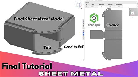
Tab - Add a tab to a sheet metal flange. Bend - Bend a sheet metal model along a reference line, with additional bend control options. Make joint - Convert the intersection of two walls into a joint feature, either a bend (walls joined by cylindrical geometry) or a rip (small gap between two walls). Corner - Modify a corner type and relief scale. When a sheet metal model is active (in the process of being created or edited), additional tools are available: Flange - Create a wall for each edge selected, connected to the selected edge with a bend.; Tab - Add a tab to a sheet metal flange.; Make joint - Convert the intersection of two walls into a joint feature, either a bend (walls joined by cylindrical geometry) .I would like to create a plate of 2000x1000mm in 3d bends. The plate is then used in a receptacle so that the oil of water automatically flows to the lowest point through the 3 bends.Your sheet metal thickness was set to 1.2mm on a huge boat, and the bend radius was set to 0.1. Typically you want your bend radius to be >= 1/2 Thickness. The long piece that forms the keel would be a really awkward part in real life.
Then do the thicken sheet metal and add the two fold features (using the lines in the sketch for the folds), and mirror the part at the end. 1 glen_dewsbury Member Posts: 763So, I have the 3D model correct and the flat sheet metal view correct. But, when I try to create a drawing, it doesn't come out right. Interestingly, the phantom view I see just before I click to place the view on the drawing sheet, is also correct but when I do click, bend lines disappear leaving me with a drawing that can't be used.For the first bend you can use the default flat pattern and dimension to the bend line. For the second bend and gauging off the bent flange use the configuration of the top view, show tangents, put a center line between the tangents of the .Part 1: I think you are asking for expanded sheet-metal correct? That could possibly be done with a custom feature script. but is not a built in function of sheet-metal.
Learn more about how to design with this versatile material in Onshape. Resource Center > Videos > Designing in Sheet Metal . VIDEO DURATION: 11:47 February 13, 2017. Designing in Sheet Metal. CAD. Sheet metal is lightweight, inexpensive, and easily formed into almost any shape. . Sheet metal is lightweight, inexpensive, and easily formed .Hello, is there a way to work bending with bending allowance and bending deduction instead of using K Factor? We have bending tables for all tools, materials and sheet thicknesses. So it can be bent to 0.1mm tolerance. With the K factor, this is only an approximation and more suitable for locksmiths. Google is responsible for the bad translation
Can you put a hole through a sheet metal bend in onshape? 2. Comments. Jake_Rosenfeld Moderator, Onshape Employees, Developers Posts: 1,646. October 2017. Hi @wayne_schafer! As of right now, you can only make cuts that cut entirely through the bend (and all cuts are made against the folded model, not the flat): This is as close as I can get with Onshape and would still need to weld the blue to the gray instead of having a simple 3 degree crack bend. 5 lines should loft to 5 lines in a "sheet metal loft" command that adds corner crack bends where surfaces aren't truly planar. Onshape's sheet metal is otherwise amazing. When a sheet metal model is active (in the process of being created or edited), additional tools are available: Flange - Create a wall for each edge selected, connected to the selected edge with a bend.; Tab - Add a tab to a sheet metal flange.; Make joint - Convert the intersection of two walls into a joint feature, either a bend (walls joined by cylindrical geometry) .This is why we use a bend table, so we can ignore the radius, we have on all the same deduction, just with the thickness the angle and the die as settings. And there are just few die for each thickness. SW, Inventor, Trumpf and others, all work with a bend table and deduction. This values we get directly from the bend machine producer.
I'd like to incorporate a "notched bend", as illustrated below, in a sheet metal part where a cutout needs to be closer to a bend than the bend clearance would normally allow. But every approach I've tried so far has been horribly clumsy, requiring several features and sketches, moving faces, etc. . I really have barely touched the sheet . Onshape also provides a sheet metal table listing bends and rips, where you are able to edit corner radii and joint types as well as create a drawing of the sheet metal part. Video example: Convert . The Bend calculation selected here is used as a column in the sheet metal table. Each bend may be customized and directly edited from the table.
When a sheet metal model is active (in the process of being created or edited), additional tools are available: Flange - Create a wall for each edge selected, connected to the selected edge with a bend.; Tab - Add a tab to a sheet metal flange.; Make joint - Convert the intersection of two walls into a joint feature, either a bend (walls joined by cylindrical geometry) .I'm having some trouble with a sheet metal file that I plan to Plasma Cut. Whilst I have produced a drawing that will be exported as a DXF the bend notes and lines continue to appear. I have R-clicked each part and selected "Hide Bend Notes" + Hide Bend Lines"When I implemented this in Rhino/Grasshopper there was no hope to emulate full 3D twisting that is not even normal sheet metal bending at all, but making it all work in the 2D flat pattern was relatively trivial, so then you just get the 3D model in real life as a test cut piece.

sheet metal edges onshape
Get the best deals on Green Metal Fishing Tackle Tackle Boxes when you shop the largest online selection at eBay.com. Free shipping on many items | Browse your favorite brands | affordable .
onshape sheet metal bending|onshape sheet metal models